
Designing and 3D Printing a Universal HDD/SSD Caddy for a Chenbro Server
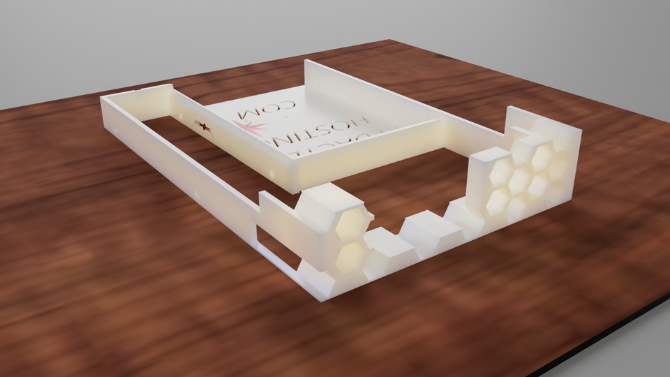
When you’re running enterprise hardware at home or in a lab, “some assembly required” is usually an understatement. Parts are often proprietary. Replacement trays and brackets get discontinued. Sellers on eBay want $40+ per sled. Shipping from overseas can mean days (or weeks) of downtime you can’t afford.
So instead of waiting for parts to show up, I designed and printed my own.
This post walks through how I modeled a universal 2.5"/3.5" drive caddy for a Chenbro SK33502 NAS chassis with a hot-swappable backplane. I’ll keep it beginner-friendly: you don’t need to already know CAD or 3D printing. The idea is to show the full path from “I need a part” to “I manufactured that part myself,” all in a few hours.
The Problem: Missing Drive Caddies = Blocked Capacity
I’m using this Chenbro chassis as storage for a locally hosted AI machine. The backplane is hot-swappable, which is great — but only if you have the trays/caddies you slide the drives into.
Without trays, I couldn’t mount additional SSDs/HDDs cleanly, and I definitely couldn’t rely on them in a production-style setup. I had two options:
- Order OEM trays (slow, expensive, sometimes inconsistent fitment).
- Design a compatible tray myself and print as many as I want.
I chose the second option.
This is the core mindset of functional 3D printing:
Instead of buying a part, you manufacture the part. Locally. On demand.
Step 1: Measuring the Real-World Requirements
Before you open any CAD software, you have to understand the physical constraints.
Here’s what I captured with a digital caliper:
- The width and height of the slot in the Chenbro hot-swap bay.
- The depth of the bay (how far the tray needs to go in so the drive’s SATA/SAS connector lines up with the backplane).
- The latch / rail geometry: basically the “rails” or guides on the side that slide the tray in and keep it aligned.
- Mounting hole positions for both 2.5" SSDs and 3.5" HDDs.
Why this matters: tolerances in server chassis are tight. If you’re off by even 0.5 mm in the wrong place, the tray will jam or refuse to seat all the way, and you’ll never hit the backplane connector cleanly.
I also looked at airflow. Enterprise gear expects drives to sit in shaped trays that guide airflow past the drive bodies. If you block that airflow with solid plastic, you’re basically baking your own components. So I already knew I wanted venting cutouts.
Deliverables from this phase:
- Target outer dimensions of the tray
- Wall thickness I’m comfortable printing
- Drive screw locations
- Clearance for airflow
Once I had those, I could move into CAD.
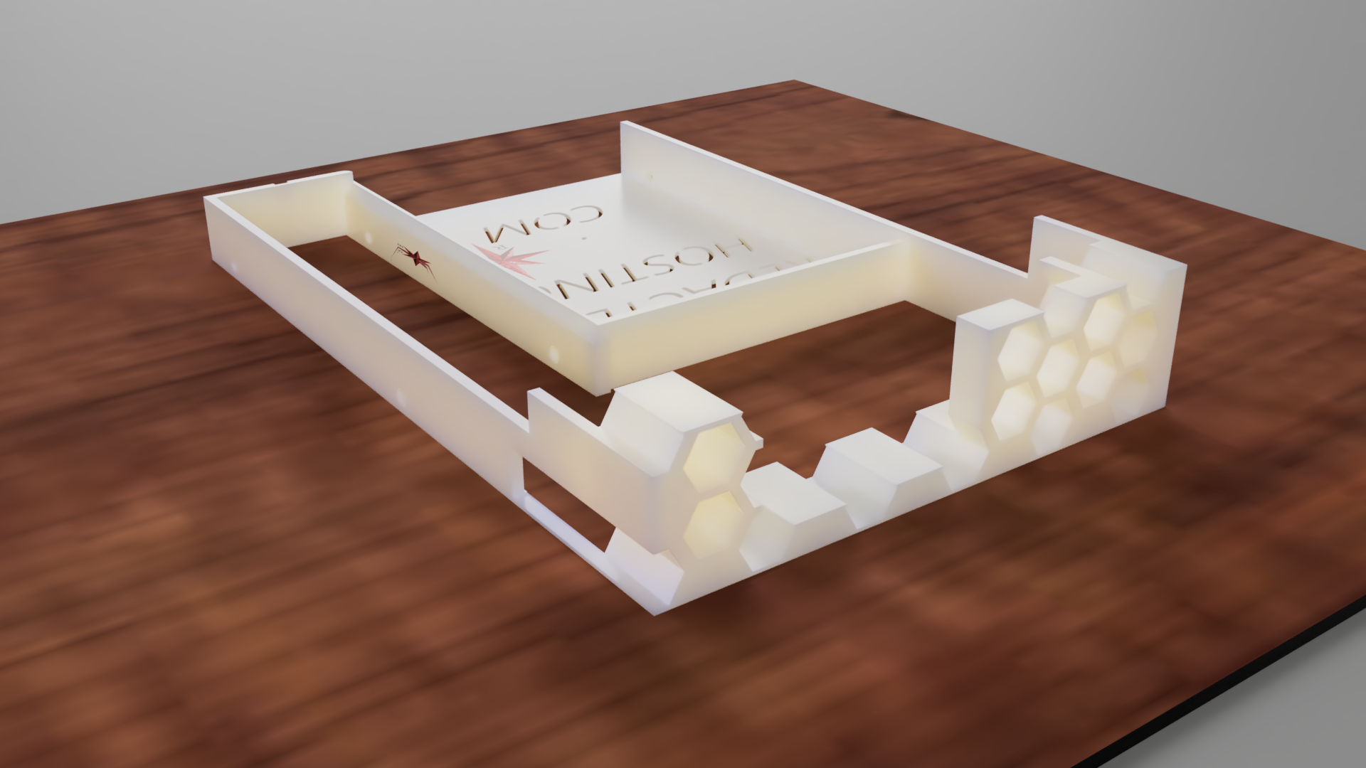
Step 2: Modeling the Tray in Fusion 360
I used Fusion 360 to build the caddy because it makes parametric design straightforward. “Parametric” just means I can tie dimensions to variables. If I later decide I need 0.4 mm more clearance on the side rails, I don’t have to redraw the whole model — I just change one number.
My workflow in Fusion 360:
- Base Profile Sketch
I started with a 2D sketch of the tray’s footprint: basically the shape that slides into the chassis bay. This defined length, width, and the rail geometry. - Extrusion to Create the Body
I extruded that sketch to the correct height so it has physical volume. Now I’ve got a basic brick that would fit in the slot. - Drive Mount Features
I added internal surfaces and standoffs where the 2.5" or 3.5" drive would sit. This is where precision matters — the drive needs to land so its connector naturally lines up with the backplane when fully inserted.- For 2.5" SSDs, I added mounting posts/screw holes in the correct SATA mounting pattern.
- For 3.5" HDDs, I added alternative mounts so the same tray could support either form factor. That’s what makes it “universal.”
- Structural Ribs and Reinforcement
PLA and PETG are strong enough for trays, but thin walls can flex. I added ribs (small vertical supports) in Fusion instead of just making the whole thing thicker. Ribs give strength without wasting filament or blocking airflow. - Weight and Airflow Cutouts
I cut out material in non-critical areas:- reduces print time,
- reduces weight,
- and lets air move across the drive faces.
- Front Handle / Pull Tab
Finally, I modeled a front tab so I can pull the tray out like a normal hot-swap sled. There’s no point having a working tray if you can’t remove it cleanly during maintenance.
By the end of this stage, Fusion 360 had a fully defined part: dimensions locked in, holes in the right places, airflow built in, and a functional handle.
Step 3: Digital Validation (aka “Does This Actually Work Before I Print It?”)
One of the underrated parts of CAD is the ability to sanity-check before wasting filament.
In Fusion 360 I did a few quick checks:
- Clearance Check: I measured the outer width and compared it to my chassis slot width minus ~0.2–0.4 mm. That small offset is intentional. You want a snug slide, not a friction weld.
- Backplane Alignment: I measured from the front face of the tray to the drive connector location and compared that to how deep the bay is before the SATA/SAS backplane. This is how you avoid stressing the connector.
- Wall Thickness: I confirmed that the thinnest structural features were still a few nozzle-widths thick so they’d actually print.
At this point, the model wasn’t just “pretty.” It was manufacturable.

Step 4: Export, Slice, and Print
Once I was happy with the model, I exported it from Fusion 360 as an STL and moved to the slicer.
(Quick explainer for beginners: the slicer is the software that turns a 3D model into actual printer instructions. You choose material, layer height, infill %, etc., and it generates G-code your printer understands.)
Print decisions:
- Material: PETG or similar is a good choice here because it has better heat resistance and toughness than basic PLA, and these trays will sit in a warm chassis under load.
- Layer Height: I went with a practical layer height (not ultra-fine detail). This is a functional part, not a display piece.
- Infill: I didn’t need 100% solid plastic. With ribs designed into the model, moderate infill is enough to keep the tray rigid.
- Supports: Minimal. I tried to design the model so it would mostly print without crazy overhangs that need support.
The result? Reliable trays without a ton of wasted material.
I printed five caddies in just a couple hours. That’s five drives I can now mount in the Chenbro chassis and put to work immediately in the AI server.
Step 5: Fitment and Real-World Use
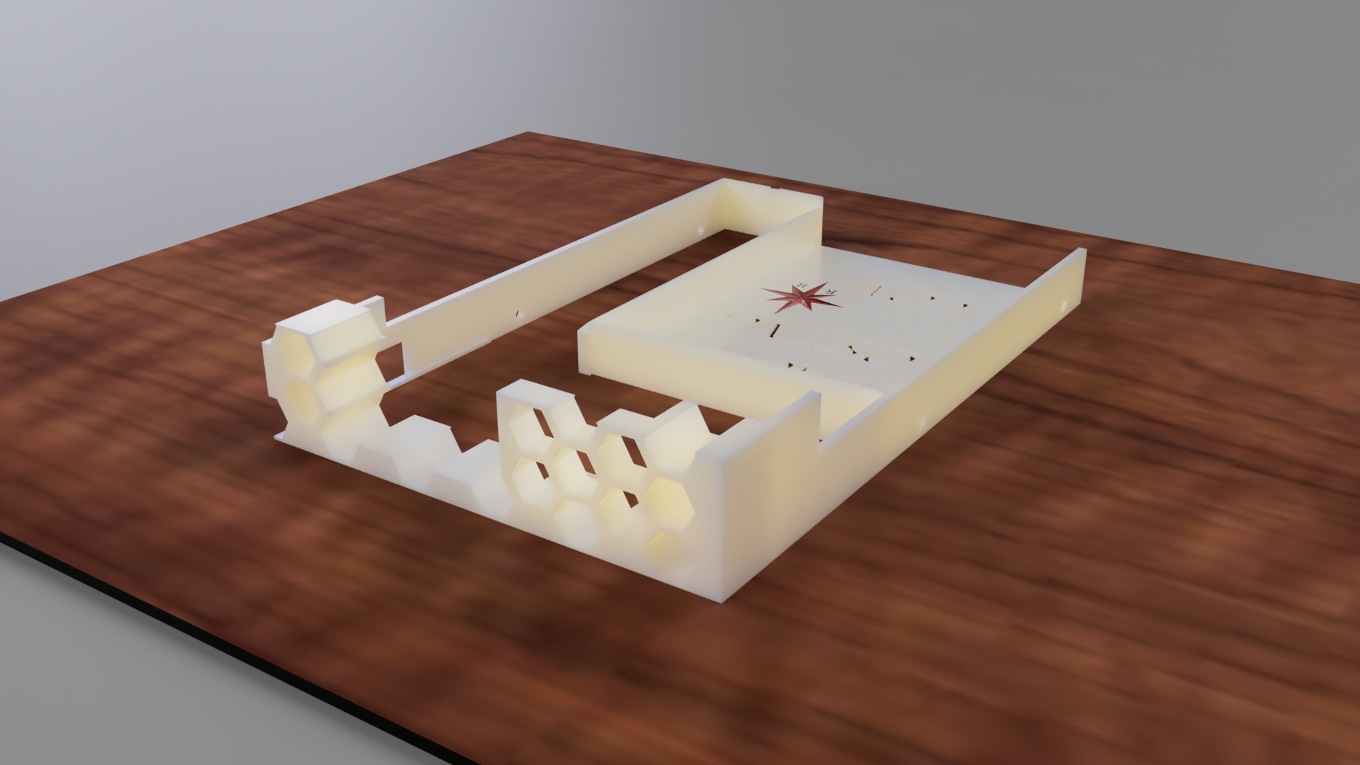
After printing, I did a test fit:
- The tray slides into the Chenbro bay.
- The drive seats cleanly.
- The front tab gives me enough leverage to pull it back out.
- The backplane connector lines up without forcing anything.
This is the moment where a digital design becomes real infrastructure. Now these aren’t “test parts” — they’re part of production storage for a local AI box.
Why This Matters (Beyond Just “Cool, I Printed a Thing”)
This project is not just about saving money (even though you do). It’s about control and uptime.
1. No downtime waiting for shipping
If a drive dies or I want to expand storage, I don’t have to pause work and hope a reseller ships the correct OEM sled. I can just print another tray on demand and be back online.
2. Vendor independence
A lot of enterprise gear quietly assumes you’ll always go back to the original vendor for spares. That’s great for them, not always great for you. Designing your own trays means you’re not stuck.
3. Scalable and repeatable
Once the CAD is done, printing five trays vs. one tray is basically just print time. I printed five for the AI machine with almost no extra effort.
4. Modifiable
If I want to:
- add labeling,
- add vibration isolation,
- tweak airflow for high-rpm HDDs,
- or adapt this tray for another chassis…
…I don’t have to “buy version 2.” I just design version 2.
That’s the real power here: you’re building a hardware library for your own lab.
For People Who Are New to 3D Printing
If you’ve never touched CAD or a printer before, here’s the high-level pipeline you just watched:
- There’s a need.
“I’m missing a drive tray for my Chenbro hot-swap bay.” - Capture reality.
Measure everything that matters (widths, depths, screw holes, airflow needs). - Model it in CAD.
Use Fusion 360 (or similar) to build a 3D version of the part with exact dimensions. - Validate digitally.
Make sure it looks printable and will align with real-world connectors. - Slice it.
Convert the 3D model into printer instructions. - Print it.
Produce a physical part on your own hardware, immediately. - Deploy it.
Install the part in your system — in my case, an enterprise-style NAS chassis feeding a locally hosted AI machine.
That’s it. You went from “this part doesn’t exist in my house” to “this part is now running in production” without waiting on anyone else.
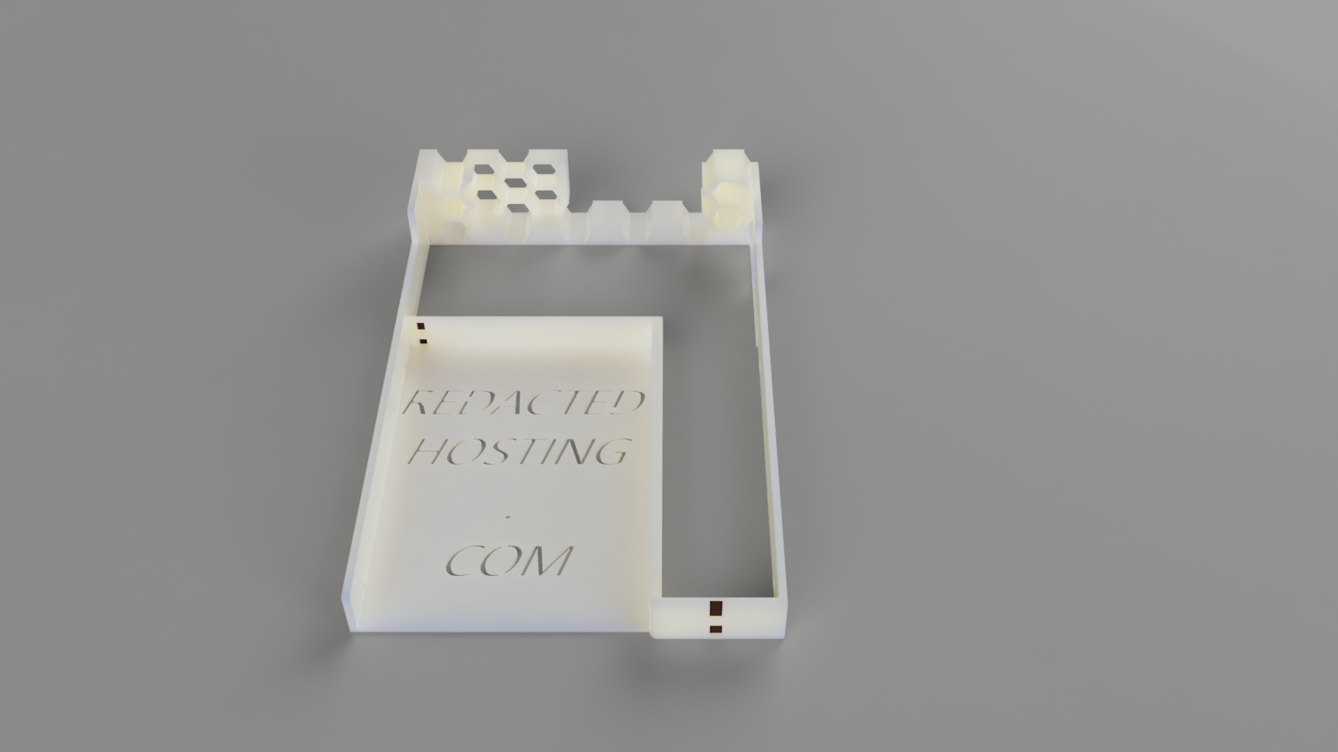
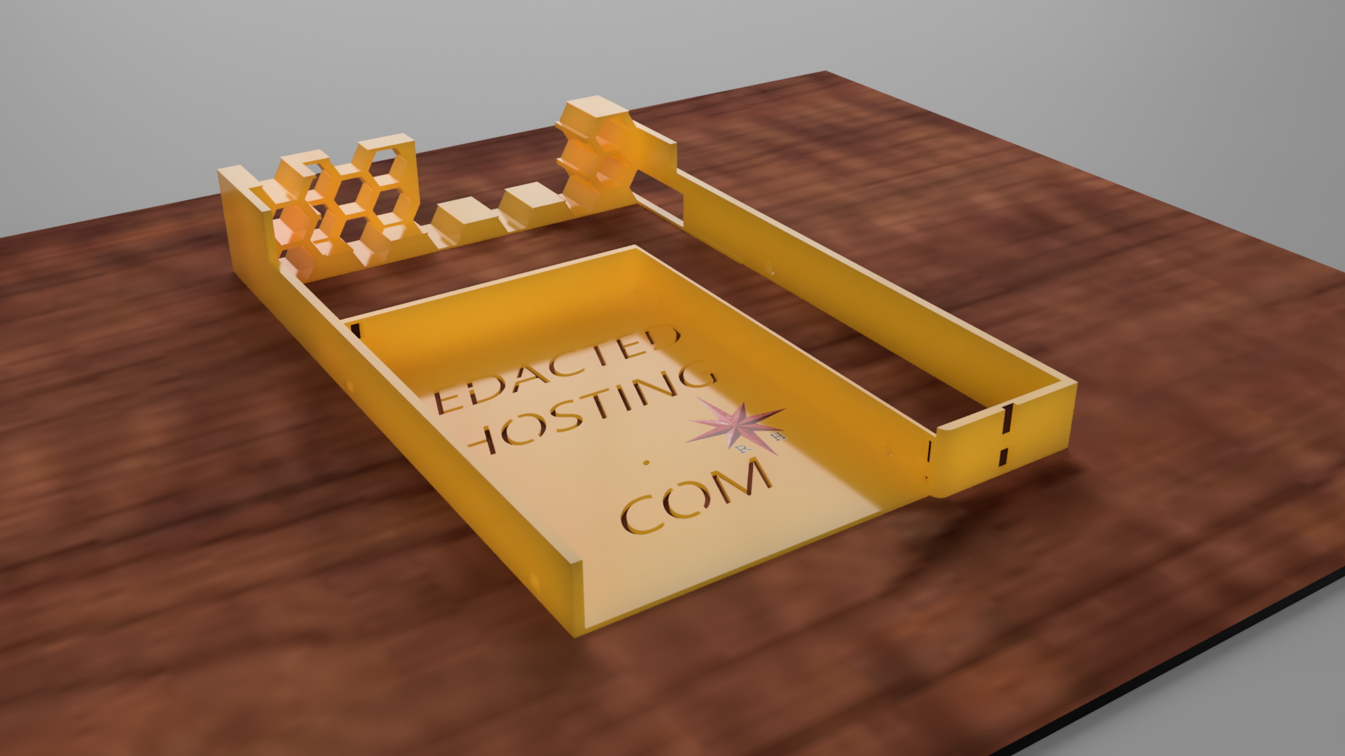
The universal HDD/SSD caddy tray started as a workaround for missing Chenbro sleds and ended up as a repeatable, locally manufacturable part for my lab. It supports 2.5" and 3.5" drives, slides into a hot-swappable backplane, and it’s already in service. If you would like to download: File link
This is what I love about modern CAD + 3D printing: you’re not just consuming hardware anymore — you’re authoring it.
If you’re running homelab or small enterprise gear and you’re stuck waiting on some $30 piece of stamped metal from across the world, consider this your sign: measure it, design it, print it.